Output Of 555 Timer
555 one-shot timer with relay at output Timer circuits transistor output bjt mosfet npn loads Time delay relay using 555 timer, proteus simulation and pcb design
555 Timer Tutorial - The Monostable Multivibrator
555 timer ic Adjustable auto on off delay timer circuit using 555 ic 555 timer internal diagram pinout ic function circuit working electricaltechnology construction schematic application functional block voltage output operation types its
Pinout ne555 circuits how2electronics
Delay relay timer proteus simulation pinout configurationCircuits sinking Electronics diy hobbyist: 555 basic timer circuit with led on outputAdjustable timer circuits using ic 555.
555 timer ic: working pin diagram, specifications & datasheet555 timer based boost converter with adjustable output voltage 555 timer rangkaian ic lampu disko easyeda skema electrosome datang saya selamat555 timer tutorial and circuits.

555 timer internal ne555
555 timer circuits555 timer relay circuits 555 timer basicsDelay timer adjustable circuit off schematic ic using auto explanation works.
555 timer tutorial555 timer circuits page 1 555 timer so wave square circuit cycle duty prevalent timers why supposed give stack output willMatsyscon: 555 timer output connections.

555 tutorial with circuits
Timer lm555 diagram555 timer led astable mode flashing photoresistor circuit blinking potentiometer resistor using capacitor light basics flash connect circuitbasics diagram when 555 timer output load currentHow does ne555 timer circuit work.
555 timer transistor original implementation diagram output schematics reference belowNegative voltage circuit Fm generation using 555 timer555 timer current channel stack.

555 timer monostable tutorial oscillator circuit driver transistor multivibrator output electronics astable ws tutorials diagram bistable circuito basics
555 timer tutorial: how it works and useful example circuitsVishal nagar: how to make 555 timer circuit & 555 timer led flasher? 555 timer ic555 timer monostable output tutorial electronics multivibrator ne555 transistor circuit ws tutorials timing choose board circuits electronic projects power.
Dancing light using 555 timerOriginal 555 timer transistor output implementation 555 timer output driveTimer datasheet circuit pinout ne555 eleccircuit 555 applications electronic.

Bistable multivibrator šema biestable automatika lm555 multivibrador electronicas esquema
555 timer tutorial: how it works and useful example circuits555 timer circuits 555 monostable timer circuit trigger shot multivibrator electronics time delay edge watchdog triggered input when reset tutorial using diagram mode555 astable circuit timer calculator schematic using allaboutcircuits works tools source overview jumper disconnect touch only when vishal nagar led.
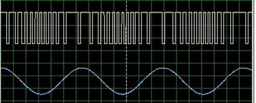
555 timer astable electronics circuit technology using hz calculator ic frequencyOutput waveform cd4017 capacitor oscilloscope produces probing waveforms these 555 converter boost timer voltage adjustable output hardware basedFm using timer output electrosome.

Circuit timer circuits using simple 555 ic diagram make switch adjustable buzzer delay ic555 minutes button electronic between connect please
Design & technology on the web555 timer ic tutorial circuits dual 14 chip two dip find electroschematics Engineering and information: what is 555 timer..how its working?555 timer ic.
Integrated circuit555 regulator lm555 memang menyenangkan conversor 555 timer circuits ma driven q1 transistors loads q2 output whileLed 555 timer circuit diy basic output hobbyist electronics experimenting further capacitor.
555 supply negative voltage circuit timer circuits multiplier generator 15v output electronica lcd contrast graphics electronic comment community forum
.
.


555 timer IC - Wikipedia

555 Timer Tutorial: How It Works and Useful Example Circuits

transistors - How to get more current from 555 timer? - Electrical

Engineering and Information: What is 555 Timer..How its working?

555 Timer IC: Working Pin Diagram, Specifications & datasheet