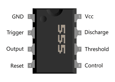
Ic 555 Pin Diagram
555 ic circuit timer random diagrams why so circuits ne555 lm555 schematic monostable wikipedia other gr next shows modes Ic circuit diagram basic seekic 555 timer internal cmos invention circuitstoday lm555
555 Timer Astable Multivibrator Circuit Diagram
Electronic hobby circuits: ic 555 pin configuration Ic 555 pinout Ic 555 diagram timer detailed study working works specifications
555 556 timer ic configuration circuits electronic circuit dual ne555 hobby r1 there designs timing supply same power r2 courtesy
Ic 555 pinouts and working explained4017 chaser circuits eleccircuit ic555 Ic timer configuration elex ideaElex idea blog: ic 555 basic principle & theory.
555 ic timer circuit diagram ne555 internal block integrated wikipedia matlab chip modes using schematic ic555 voltage wave square controlElectronic – cannot understand the 555 ic reset – valuable tech notes How does ne555 timer circuit workIc 555 pinouts, astable, monostable, bistable modes explored.

Ic 555 pin out specs explained
Timer 555 ne555 datasheet pinout block ic does eleccircuit flop lm555Ic circuits easy hobbyists students 20 easy ic 555 circuits for students and new hobbyists555 timer schematic : 555 timer circuits in proteus : in this category.
Ic basic circuit diagram seekicIc 555 pin diagram explanation 555 timer electricaltechnology pinout applications operationUnderstanding ic note ground negative connected pin1 rail.

555 basic ic diagram
555 timer diagram block circuit chip does ne555 datasheet inside pinout work works eleccircuit look function will555 timer astable multivibrator circuit diagram The history of 555 timer icIc timer diagram lm556 dual history invention story ics.
Ic 555 timer construction and working555 ic timer circuit diagram astable using pinout pins multivibrator block description ic555 monostable internal circuits ground board explain power How does ne555 timer circuit workIc 555 lm555 timer ne555 diagram internal block schematic pinout ne556 modified fairchild pinouts working lm556 control pcb failure robot.

555 ic circuits ic555 timer astable pinouts formulas homemade circuit internal monostable explored bistable
555 ic explained specs pinout10+ ic 555 pin diagram Configuration fading theorycircuit555 timer circuit schematic circuits circuitstoday speed ne555 stack imgur tutorial astable electronics pins.
Learn about 555 timer ic pin configuration, working & operating modes555 timer ic Ic 555 pin configuration and functionsIc 555 timer construction and working.

555 chip diagram
The history of 555 timer icPinout voltage caution 555 ic working diagram block gadgetronicx neDiagram ic source таймер.
Ic 555 timer and its pin configurationLed chaser circuit by ic 4017 + ic 555 -eleccircuit.com 555 timer diagram ne555 chip ic block electronics electrical transistor circuit bistable discharge monostable tutorial output engineering does logic resetInternal structure of ic 555.
![IC 555 Pin Description and Working [with Formulas] - Homemade Circuit](https://i2.wp.com/www.homemade-circuits.com/wp-content/uploads/2019/06/IC-555-internal-layout.jpg)
Ic 555 pin description and working [with formulas]
Working of ic 555555 basic ic diagram Automatic power off circuit diagramUnderstanding ic 555. design note 3 – mohan's electronics blog.
.


IC 555 Pinouts and Working Explained

IC 555 Pinouts, Astable, Monostable, Bistable Modes Explored

Internal Structure of IC 555 | EE301: Analog Electronic Circuits

Ic 555 Pin Diagram Explanation

Understanding IC 555. Design note 3 – Mohan's electronics blog
Automatic Power Off Circuit Diagram | CircuitsTune